873
FREE
circuits!
FREE
circuits!
How to build Low Voltage Alarm
November 16, 2010 - category: Current and voltageDescription
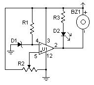
This low voltage circuit can be used to monitor batteries and other volatile sources of current for problems. The circuit sounds an alarm and lights an LED, but can be interfaced to any number of other circuits for many different uses.
Circuit diagram
Parts:
- R1, R3 1K 1/4W Resistor
- R2 5K Pot
- U1 LM339 Voltage comparator IC
- D1 1N5233B Zener Diode
- D2 LED
- BZ1 Piezo Buzzer
- MISC Board, wire, socket for IC
Notes:
- The circuit will operate from 9V to 12V.
- Adjust R2 until the alarm goes off at the correct voltage.
circuit from http://www.aaroncake.net/


 This category