FREE
circuits!
Timer circuit diagrams
August 8, 2010
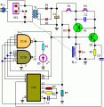
The two circuits illustrate using the 555 timer to close a relay for a predetermined amount of time by pressing a momentary N/O push button. The circuit on the left can be used for long... [more]
August 8, 2010
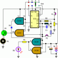
The circuit illustrates generating a single positive pulse which is delayed relative to the trigger input time. [more]
August 8, 2010
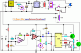
Here's a power-on time delay relay circuit that takes advantage of the emitter/base breakdown voltage of an ordinary bi-polar transistor. The reverse connected emitter/base junction of a 2N3904 transistor is used as an 8 volt... [more]
August 8, 2010
The two circuits illustrate opening a relay contact a short time after the ignition or ligh switch is turned off. The capacitor is charged and the relay is closed when the voltage at the diode... [more]
August 8, 2010
Most thefts happen after midnight hours when people enter the second phase of sleep called ‘paradoxical’ sleep. Here is an energy-saving circuit that causes the thieves to abort the theft attempt by lighting up the... [more]
circuit from:http://www.extremecircuits.net/2010/01/midnight-security-light-circuit.html
August 8, 2010
Protect your home appliances from voltage spikes with this simple time delay circuit. Whenever power to the appliances is switched on or resumes after mains failure, the oscillator starts oscillating and D5 blinks. This continues... [more]
circuit from:http://www.extremecircuits.net/2009/07/safety-guard.html
August 8, 2010
The purpose of this circuit is to power a lamp or other appliance for a given time (30 minutes in this case), and then to turn it off. It is useful when reading at bed... [more]
circuit from:http://www.extremecircuits.net/2009/12/bedside-lamp-timer-circuit-schematic.html
August 8, 2010
This circuit is intended for alerting purposes after a certain time is elapsed. It is suitable for table games requiring a fixed time to answer a question, or to move a piece etc. In this... [more]
circuit from:http://www.extremecircuits.net/2009/12/very-useful-timed-beeper-circuit.html
August 8, 2010
This circuit turns-off an amplifier or any other device when a low level audio signal fed to its input is absent for 15 minutes at least. Pushing P1 the device is switched-on feeding any appliance... [more]
circuit from:http://www.extremecircuits.net/2010/01/amplifier-timer-circuit-schematic.html
August 8, 2010
This circuit was developed since a number of visitors of this website requested a timer capable of emitting a beep after one, two, three minutes and so on, for jogging purposes. As shown in the... [more]


 This category