FREE
circuits!
How to build Dual Relay Driver Board Circuit Schematic
September 30, 2010 - category: SwitchesDescription
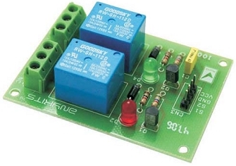
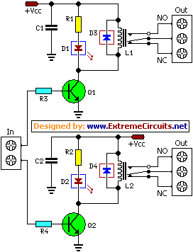
A simple and convenient way to interface 2 relays for switching application in your project. This relay driver boosts the input impedance with a regular BC547 NPN transistor (or equivalent). Very common driver. It can drive a variety of relays, including a reed-relay. Transistor Q1and Q2 are a simple common-emitter amplifier that increases the effective sensitivity of the 12 volt relay coil about a 100 times, or in other words, the current gain for this circuit is 100. Using this setup reduces the relay sensitivity to a few volts. R3 and R4 restricts the input current to Q1 and Q2 to a safe limit. Diodes D3 and D4 are EMF dampers and filter off any sparking when the relay de-energizes.
Picture of the project:
Circuit diagram:
Parts:
- R1-R2 = 1K
- R3-R4 = 5.6K
- C1-C2 = 100nF-63V
- D1-D2 = Red LED
- D3-D4 = 1N4001
- L1-L2 = 12V Relay
- Q1-Q2 = BC547
Specification:
- Input - 12 VDC @ 84 mA
- Output - two SPDT relay
- Relay specification - 5 A @ 230 VAC
- Trigger level-2~5VDC
- Berg pins for connecting power and trigger voltage
- LED on each channel indicates relay status
circuit from http://www.extremecircuits.net/2010/01/dual-relay-driver-board-circuit.html


 This category