FREE
circuits!
How to build Capacitive Sensor Circuit Diagram
September 27, 2010 - category: Touch sensorDescription
The purpose of this circuit is to animate shop-windows by means of a capacitive sensor placed behind a post-card-like banner. The card is placed against the glass inside the shop-window, and the visitor can activate the relay placing his hand on the card, from the outside. Especially suited for toy-shops, the circuit can activate model trains, small electric racing cars, lights etc. Further applications are left at user's imagination. Adopt it to increase the impact of your shop-window on next Christmas season!
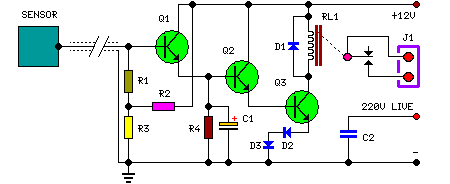
Q1, Q2 & Q3 form a high impedance super-Darlington that drives the relay, amplifying the 50 or 60Hz alternate mains-supply frequency induced in the sensor by the human body. C1, D2 & D3 ensure a clean switching of the relay. Power supply can be any commercial wall plug-in transformer adapter with rectifier and smoothing capacitor, capable of supplying the voltage and current necessary to power the relay you intend to use.
Circuit diagram:
Parts:
- R1,R2_____1M 1/4W Resistors
- R3,R4____47K 1/4W Resistors
- C1_______10µF 25V Electrolytic Capacitor
- C2______470pF 630V Ceramic or Polyester Capacitor
- D1-D3____1N4002 100V 1A Diodes
- Q1-Q3_____BC337 45V 800mA NPN Transistors
- RL1_______Relay with SPDT 2A @ 220V switch
- Coil Voltage 12V. Coil resistance 200-300 Ohm
- J1________Two ways output socket
- Sensor____Aluminum or copper thin sheet with the dimensions of a post-card,
- glued at the rear of the same (about 15x10.5 cm.)
- Thin screened cable
Note:
For proper operation, circuit ground must be connected via a small value, high voltage-rating capacitor to one side of the mains supply socket. The "Live" side is the right one.
circuit from http://www.redcircuits.com/Page22.htm


 This category