FREE
circuits!
How to build Electronic Candle Blow Out Schematic
October 3, 2010 - category: Sound sensorDescription
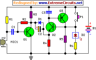
This design was developed by request of a correspondent having made a sort of LED candle and needing to switch off the LED with a puff. This simple, easy to build gadget can be useful as a prop for Halloween and Christmas season, shows and the like. Q2 & Q3 form a self-latching pair that start operating when P1 is pushed: in this way the LED (or bulb) will illuminate steadily. When someone emits a strong puff in the vicinity of the small electret microphone,
The resulting signal will be greatly amplified by Q1 and a rather long positive pulse (shaped by D1 and C2) will reset the self latching pair through the Emitter of Q2. The very low (and unusual) value of C1 acts as a simple high-pass filter, in order to prevent that normal speech or environmental noise shut off the device. Obviously, such a simple filter cannot be very discriminating, therefore, not only a strong puff will reset the circuit but also a loud shout, blow, clap or stroke.
Circuit diagram:
Parts:
- R1 = 10K
- R2 = 1M
- R3 = 1K
- R4 = 4.7K
- R5 = 10K
- R6 = 100R
- C1 = 100pF-63V
- C2 = 10µF-25V
- C3 = 100nF-63V
- D1 = 1N4148
- D2 = Red LED
- P1 = SPST Pushbutton Switch
- B1 = 3V Battery (2 x 1.5V AA, AAA Cells in series etc.)
- Q1 = BC550C-45V 100mA NPN Transistor
- Q2 = BC337-45V 800mA NPN Transistor
- Q3 = BC327-45V 800mA PNP Transistor
- MIC1 = Miniature electret microphone
Notes:
- A small bulb can be used in place of the LED. In this case a 3 - 3.5V, 0.7W (200mA) incandescent bulb can be used satisfactorily. Therefore, D2, R5 and R6 must be omitted, the bulb wired in place of R5 and R4 value changed to 1K5.
- Using a bulb instead of the LED, a 1.5V battery supply could also be used. A 1.5V, 0.3A incandescent bulb will work, but R4 must be replaced by a 470 Ohm Trimmer, adjusted to allow a reliable circuit operation.
- Please note that the circuit will draw a small current even when the LED or bulb are off. This current is about 1.2mA for the LED version of the circuit, 1.5mA for the 3V bulb version and 1mA for the 1.5V bulb version. Therefore, in some circumstances, the addition of a power on-off switch could be necessary.
circuit from http://www.extremecircuits.net/2010/01/electronic-candle-blow-out-schematic.html


 This category