FREE
circuits!
How to build Voice activated switch
October 5, 2010 - category: Sound sensorCircuit diagram
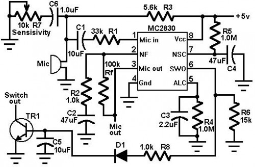
This circuit uses an MC2830 to form a voice activated switch ( VOX ). A traditional VOX circuit is unable to distinguish between voice and noise in the incoming signal. In a noisy environment, the switch is often triggered by noise, or the activation sensitivity must be turned down. This circuit overcomes this weakness. The switch is activated by voice level above the noise and not activated by background noise. This is done by utilizing the differences in voice and noise waveforms. Voice waveforms generally have a wide range of variation in amplitude, whereas noise waveforms are more stable. The sensitivity of the voice activation depends on the value of R6. The voice activation sensitivity is reduced from 3.0dB to 8.0dB above the noise if R6 changes from 14k to 7.0k .
author: Motorola
circuit from http://www.electronics-lab.com/


 This category