FREE
circuits!
Radio circuit diagrams
December 10, 2010
This is a medium range transmitter circuit diagram. This is also improved by changing the values of the resistor. [more]
December 3, 2010
This circuit is a 73 MHz Hallogene Lamp Radio-Controlled. The purpose of it is to control the power state of a hallogene lamp by a remote control. [more]
December 2, 2010
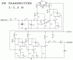
This is the schematic for an FM transmitter with 3 to 3.5 W output power that can be used between 90 and 110 MHz. Although the stability isn't so bad, a PLL can be used... [more]
November 30, 2010
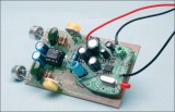
Contains information about building a small radio transmitter, which has a PCB 1.75" x 2.5" (45mm x 68 mm) and has a range of about 30 yards or so. The documentation with the circuit says... [more]
November 10, 2010
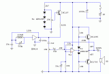
This circuit is deliberately limited in power output but will provide amplitude modulation (AM) of voice over the medium wave band. [more]
October 12, 2010
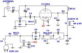
TECHNICAL CHARACTERISTICS: Tendency of catering: 220V AC Frequency of emission at FM: 88~108MHz Force of expense: max 45W (without the R3), [more]
October 5, 2010
Designed around the popular ZN414 ic this receiver covers the AM band from 550 - 1600 KHz with the values shown. For Longwave the coil needs to be changed. Use one from an old MW... [more]
September 27, 2010
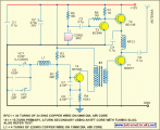
This low-cost short-wave transmitter is tunable from 10 to 15 MHz with the help of ½J gang condenser VC1, which determines the carrier frequency of the transmitter in conjunction with inductor L1. The frequency trimming... [more]
circuit from:http://www.extremecircuits.net/2010/05/simple-short-wave-transmitter.html
September 27, 2010
This stereo FM wireless microphone also makes a great quality audio link. We tested it to beyond 50 meters and it was rock solid. It’s certainly not the first wireless microphone we’ve ever published but... [more]
September 27, 2010
There are not many AM transmitters that are easier to build than this one because the inductor is not tapped and has a single winding. There is no need to wind the inductor as it... [more]
circuit from:http://www.extremecircuits.net/2010/05/simple-am-transmitter.html





 This category