FREE
circuits!
How to build Medium-Power FM Transmitter
September 27, 2010 - category: FM transmitterDescription
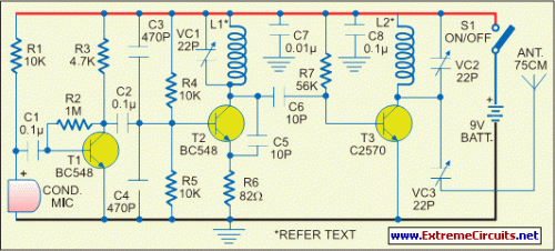
The range of this FM transmitter is around 100 meters at 9V DC supply. The circuit comprises three stages. The first stage is a microphone preamplifier built around BC548 transistor. The next stage is a VHF oscillator wired around another BC548. (BC series transistors are generally used in low-frequency stages. But these also work fine in RF stages as oscillator.) The third stage is a class-A tuned amplifier that boosts signals from the oscillator. Use of the additional RF amplifier increases the range of the transmitter.
Circuit diagram:
Coil L1 comprises four turns of 20SWG enameled copper wire wound to 1.5cm length of a 4mm dia. air core. Coil L2 comprises six turns of 20SWG enameled copper wire wound on a 4mm dia. air core. Use a 75cm long wire as the antenna. For the maximum range, use a sensitive receiver. VC1 is a frequency-adjusting trimpot. VC2 should be adjusted for the maximum range. The transmitter unit is powered by a 9V PP3 battery. It can be combined with a readily available FM receiver kit to make a walkie-talkie set.
author: EFY Mag
circuit from http://www.extremecircuits.net/2010/05/range-of-this-fm-transmitter-is-around.html


 This category