FREE
circuits!
How to build Discrete PWM Generator Circuit
August 8, 2010 - category: PWM and power controlDescription
PWM waveforms are commonly used to control the speed of DC motors. The mark/space ratio of the digital wave-form can be defined either by using an adjustable analogue voltage level (in the case of a NE555 based PWM generator) or digitally using binary values. Digitally derived PWM waveforms are most often produced by the timer/counter modules in microcontrollers but if you do not want to include a microcontroller in your circuit it’s also quite simple to generate the signals using discrete logic components.
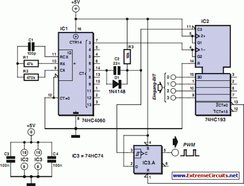
Circuit diagram:
An extension of the circuit shown can produce two PWM wave-forms from an 8-bit digital input word. Each signal has 15 values. The 8-bit word can be produced for example from an expansion board fitted in a PC or from an 8-bit port of a processor which does not have built-in PWM capability or from a laptop’s printer port. The mark/space ratio is only programmable up to 15/16 rather than 16/16; a binary input of 0000 produces a continuous low on both outputs turning both motors off.
Similar circuits often employ a dedicated ‘enable’ input to turn the motors off but it is not necessary in this design. The diagram shows the circuitry required to produce just one waveform. For the full two channel circuit it is necessary to use an additional 74HC193. The clock signal produced by the HCF4060 generator can be used to drive both channels and the free flip flop in the 74HC74 package can be used for the second channel (the corresponding pin numbers are shown in brackets). Altogether the entire two channel circuit can be built using just four ICs.
circuit from http://www.extremecircuits.net/2010/05/discrete-pwm-generator-circuit.html


 This category