FREE
circuits!
How to build Mobile Phone and iPod Battery Charger Circuit
August 4, 2010 - category: Battery chargerDescription
Using the USB port on your computer to charge your player’s batteries is not always practical. What if you do not have a computer available at the time or if you do not want to power up a computer just for charging? Or what if you are traveling? Chargers for Mobile Phones iPods and MP3 players are available but they are expensive and you need separate models for charging at home and in the car.
This charger can be used virtually anywhere. While we call the unit a charger, it really is nothing more than a 5V supply that has a USB outlet. The actual charging circuit is incorporated within the iPOD or MP3 player itself, which only requires a 5V supply. As well as charging, this supply can run USB-powered accessories such as reading lights, fans and chargers, particularly for mobile phones.
The supply is housed in a small plastic case with a DC input socket at one end and a USB type "A" outlet at the other end, for connecting to Mobile Phone, an iPod or MP3 player when charging. A LED shows when power is available at the USB socket. Maximum current output is 660mA, more than adequate to run any USB-powered accessory.
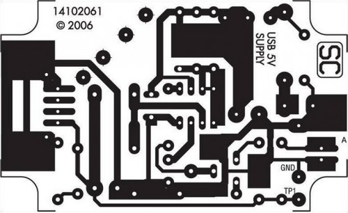
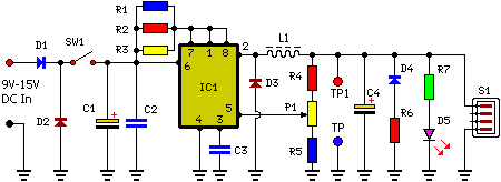
Pictures, PCB and Circuit Diagram:
Parts:
- P1 = 1K
- R1 = 1R-0.5W
- R2 = 1R-0.5W
- R3 = 1R-0.5W
- R4 = 1K
- R5 = 560R
- R6 = 10R-0.5W
- R7 = 470R
- C1 = 470uF-25V
- C2 = 100nF-63V
- C3 = 470pF
- C4 = 100uF-25V
- D1 = 1N5404
- D2 = 1N4001
- D3 = 1N5819
- D4 = 5.1V-1W Zener Diode
- D5 = 5mm. Red LED
- L1 = 220uH
- S1 = USB 'A' Type Socket
- SW1 = On/Off Switch
- IC1 = MC34063A
Specifications:
- Output voltage ----------------------5V
- Output current ---------------------660mA maximum for 5V out
- Input voltage range ------------------9.5V to 15V DC
- Input current requirement ----------500mA for 9V in, 350mA for >12V input
- Input current with output shorted--- 120mA at 9V in, 80mA at 15V in
- Output ripple ------------------------14mV (from no load to 660mA)
- Load regulation ----------------------25mV (from no load to 660mA)
- Line regulation ----------------------20mV change at full load from 9 to 18V input
- No load input current ----------------20m
(The specification for the computer USB 2.0 port requires the USB port to deliver up to 500mA at an output voltage between 5.25V and 4.375V).
The circuit is based around an MC34063 switch mode regulator. This has high efficiency so that there is very little heat produced inside the box, even when delivering its maximum output current. The circuit is more complicated than if we used a 7805 3-terminal regulator but since the input voltage could be 15V DC or more, the voltage dissipation in such a regulator could be 5W or more at 500mA. and 5W is far too much for a 7805, even with quite a large heatsink. Credit for this circuit goes to SiliconChip, A wonderful electronics magazine.
circuit from http://www.extremecircuits.net/2009/08/mobile-phone-and-ipod-battery-charger.html


 This category