873
FREE
circuits!
FREE
circuits!
How to build Remote Doorbell Warning Switch
November 26, 2010 - category: LED driverCircuit diagram
Important Note:
This circuit should only be used with the solenoid type chime doorbells, the electronic type that play tunes will not work here.
Notes:
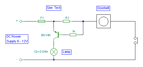
- The hardest part for this circuit was the title. It is quite easy to miss the sound of a doorbell if you are watching TV , this circuit gets round the problem by providing a visual indication, i.e. a lamp. As an alternative, a LED could also be used. You could just parallel a lamp across the doorbell, but this would mean extra drain from
- the doorbell batteries or transformer. Using a series resistor R1 actually reduces current flow , and if run from batteries, will give them a longer life. The value of R1 is chosen so that about 0.6 to 0.7 volts is dropped across it, and the doorbell should
- still ring. I used a combination of a 22 ohm resistor in parallel with a 50 ohm. The doorbell still rang and circuit operated correctly. I used to have an electromechanical counter that registered each time when someone pressed the switch....in fact, I remember a time when I had more "hits" at my doorbell then at my web site=:)
circuit from http://www.electronics-lab.com/


 This category