FREE
circuits!
How to build Electronic Dice
August 8, 2010 - category: Fun and gamesDescription
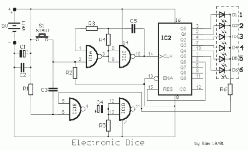
The particular circuit is substantially a generator of accidental numbers, from 1 until the 6. The clue him we see in a line from led, that each one corresponds also in a number from the 1-6, if push and leave, the S1 (push button). This movement corresponds in a movement of dice. The led that it turned on will remain turned on for five until ten seconds and afterwards it will black out, waiting for the next movement. The electronic dice, in order to imitate a real dice, needs it stops '' with one from the six LED's turned on, after each led stand for, one from the six numbers in the sides of real dice. A led turns on in sequence and then remains one led turned on, when is left switch S1. The circuit can be separated in two parts, from which the one concerns the clues, while the other gives the signals time and control. The last part of circuit is recommended by two classic circuits, the astable, that is recommended by the IC1a-c and the monostable, that is recommended by the ICΒ-D. The line of pulse that is produced by the ''anstable '' circuit is drive to the IC2. What is counter has ten exits. The pulses are drive to his entry, every by the ten exits will be activated in sequence. In this circuit, we want counter, it measures until the six. In order to we achieve this, we connect the seventh exit of 5 IC2 in entry 15 (reset) the himself. When exit 5 takes high price, it restores the counter in initial situation. The led are drive by the exits of IC2 that are in high price and will turn on when the common point in which they are connected cathode the led and R6 have low price. The R6 is connected in the exit of IC1D. This point has regularly high level and thus all the led is off (blank out). When are left the S1, the entry of IC1B, via the C3 and R1, takes low level, for small time interval and thus the exit of this gate takes high level. The C4 transmits this change in the entry of IC1D and it forces the exit of this gate to take low level, activating the clue. The R5 discharge the C4, forcing the circuit to take his previous situation, after certain seconds. It can become change of this time changing the price of R5. The R6 limits the current that passes through the led., in a safe price. The supply of circuit becomes from a battery that can bear enough, without it needs him we change, one and the circuit it does not consume energy, despite for very little time, making thus and the existence of switch, no essential.
Circuit diagram
Part List
- R1-3-5= 100Kohms
- R2= 10Kohms
- R4= 56Kohms
- R6= 470 ohms
- C1-4= 100uF 16V
- C2= 100 nF 63V MKT
- C3-5= 10nF 63V MKT
- IC1= 4011
- IC2= 4017
- D1-6= LED Red 5mm.
- S1= Push button switch
- BATT= 9V battery
circuit from http://users.otenet.gr/~athsam/electronic_dice_a.htm


 This category