FREE
circuits!
How to build Digital Roulette with Display
August 8, 2010 - category: Fun and gamesDescription
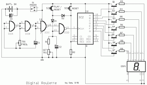
This circuit is a small digital roulette''. It is constituted by oscillator IC1, the counter IC2, the transistors Q1-7 that drive the display common cathode DSP1. The supply basically becomes from a battery 9V, but can become also from one power supply. The regulation of frequency should become in the 10HZ or little bigger, with to pontesometer TR1 combination with the C1, which we can change the capacity, changing thus and the frequency of oscillator. Bigger frequency means faster speed in ΄΄rolling΄΄ the indicate in the display. Mε the TR2 we alter the time where will last the measurement, afterwards the release of S1. With the S2 we make RESET in the display. With the S1, we make departure in the circuit and simultaneously RESET, when start after a circle. When we release the S1, the meter stops in number, then it should we press again the S1, so that begins new circle of game or we make nihilism via the S2. If comes zero then the player that makes '' mother '', it can take all the '' profits, from all the other players. In the game they can take part, from two up to nine players. The TR1-2 can be in form trimmer or potentiometer, proportionally what us accomodates.
Circuit diagram
Part list
- R1= 10Kohms
- R2-9= 1Kohms
- C1= 0.47 until 2.2uF 16V
- C2= 100uF 16V
- C3= 47uF 16V
- Q1-8= BC550
- DSP1= Display 7 segment common cathode
- IC1= 4011
- IC2= 4026
- D1-2= 1N4148
- TR1= 470Kohms trim. or pot. lin
- TR2= 100Kohms trim. or pot. lin
- S1= 1Χ2 Switch
- S2-3= Push Button normal open
- BATT= 9V Battery οr ext. supply
circuit from http://users.otenet.gr/~athsam/digital_roulette.htm


 This category