873
FREE
circuits!
FREE
circuits!
How to build 5 Band Graphic Equalizer
August 8, 2010 - category: Tone and volume controlDescription
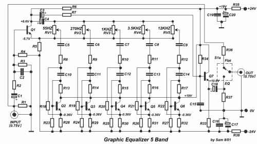
Other one unit of graphic EQ. five bands. The basic difference with the other circuits is, that I use instead of IC, transistor and the power supply, go up in +/- 24V DC, ensuring low distortion and bigger margins of overloading. With switch S1, we can isolate the EQ. inside or except operation, leaving the musical signal to pass without no alteration.
Circuit diagram
Part list
- R1-4-37= 330Kohms
- R2-7= 2.2Kohms
- R3= 120Kohms
- R5-6= 6.8Kohms
- R8....12= 1.8Kohms
- R13....15= 200Kohms
- R16= 180Kohms
- R17= 150Kohms
- R18= 1.5Kohms
- R19....22= 1Kohms
- R23....27= 220Kohms
- R28....32= 15Kohms
- R33= 10Kohms
- R34= 15Mohm
- R35-38= 220 ohms 1W
- R36= 100 ohms
- C1-3= 1uF 40V
- C2= 68pF 100V
- C4= 220uF 63V
- C5= 1uF 100V
- C6= 220nF 100V
- C7= 47nF 100V
- C8= 15nF 100V
- C9= 5.6nF 100V
- C10= 47nF 100V
- C11= 15nF 100V
- C12= 4.7nF 100V
- C13= 1.5nF 100V
- C14= 470pF 100V
- C15= 68pF 100V
- C16-19= 100nF 100V
- C17-20= 470uF 40V
- C18= 4.7uF 63V
- RV1....5= 50Kohms Lin.
- Q1.....7= BC550C
- S1= 2X2 SW
circuit from http://users.otenet.gr/~athsam/EQ_3.htm


 This category