873
FREE
circuits!
FREE
circuits!
How to build VU Meter 4
August 8, 2010 - category: Sound level meterDescription
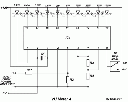
The circuit is placed parallel with the exit of power amplifier and us gives the level of signal ,from output. Changing resistance R1, in the input circuit, we adapt the indication of power, in the resistance of loudspeaker, that we use.
Circuit diagram
Part list
- R1=10Kohm for 4ohm
- R1=18ohm for 8ohm
- R2=10Kohm
- R3=390ohm
- R4=2.7Kohm
- C1=2.2uF 25V
- D1-10=LED
- S1=mini switch
- IC1=LM3915
circuit from http://users.otenet.gr/~athsam/vu_meter_4.htm


 This category