FREE
circuits!
How to build Tube Power Amplifier with EL34 - 35W
August 6, 2010 - category: Audio amplifierDescription
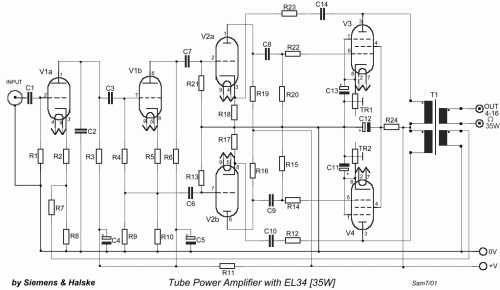
It's a classic designing of final amplifier 35 W, with two EL34 in push-pull, from the Siemens and Halske, with year of designing 24/3/1953 and code SV410/1. The amplifier it worked from 1954 until 1989, whenever it came also out except operation, with mean of operation 15 hours per day. It did not present particular damage beyond the replacement of tubes, resistances and capacitors, result of natural deterioration. A essential change became with the replacement of restoring provision from tube, with diodes. The alone problem that will exist, for those who they try his manufacture, will be the transformer of expense, (it is in effect for all the tube manufactures), one and code that exists it will help. It can be replaced with a classic transformer of expense suitable for EL34. In his manufacture it needs (it is in effect for all the corresponding circuits), enough experience and attention in high voltage, danger of ELECTRIC SHOCK.
Circuit diagram
Part List
- R1=470K 0,5W
- R2-5= 2K2 0.5W
- R3=150K 0.5W
- R4= 220K 0.5W
- R6-10= 56K 0.5W
- R7=3.9K 0.5W
- R8= 220R 0.5W
- R9= 1M 0.5W
- R11= 39K 1W
- R12-23= 180K 0.5W
- R13-21=820K 0.5W
- R14-22=5K6 0.5W
- R15-20= 680K 0.5W
- R16-19=100K 0.5W
- R17-18=3K3 1W
- R24=470R 2W
- TR1-2=470R 1W Variable (adj. 270Ω)
- C1-3-6-7=0.1uf 630V
- C2=220pF 600v
- C4-5=16uF 550V
- C8-9=0.1uF 630V
- C10-14=0.47uF 630V
- C11-13=25uF 40V
- V1=E80CC
- V2=E80CC
- V3-4=EL34
- Rectifier tube= Z2C
- T1=Audio Transformer for 2x EL34 Push Pull
circuit from http://users.otenet.gr/~athsam/Power_amplifier_EL34.htm


 This category