FREE
circuits!
How to build Four Small Transistor Alarm Circuits
August 4, 2010 - category: AlarmAlarm A
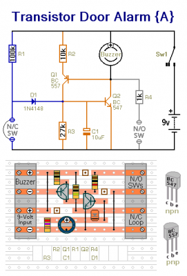
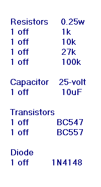
Alarm "A" is a practical version of the circuit featured in my Introduction To The Complementary Latch. It has both normally-open and normally-closed triggers. Once activated - the buzzer will go on sounding until the alarm is switched off. The standby current is less than 100uA. This is due exclusively to the value of R1. Depending on the gain of the actual transistors you're using - you may be able to increase the value of R1 - and so improve battery life.
Alarm B
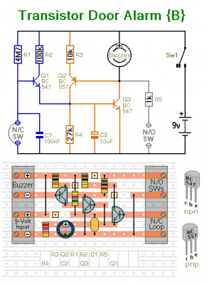
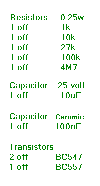
Alarm "B" is an enhanced version of circuit "A". It too has both normally-open and normally-closed triggers. And - once activated - the buzzer will go on sounding until the alarm is switched off. However, the standby current is much lower - about 2uA. So battery life should be increased 50 fold. Again - depending on the gain of the actual transistors you're using - you may be able to increase the value of R1 - and so improve battery life even further.
Alarm C
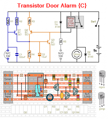
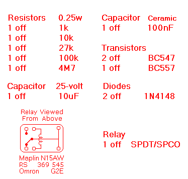
Alarm "C" is an enhanced version of circuit "B". It too has both normally-open and normally-closed triggers. And the standby current is about 2uA. But the Buzzer output has been replaced by a Siren output. The presence of the relay means that you can safely draw about 500mA from the output terminals. So you can connect a much louder sounder to the alarm.
Alarm D
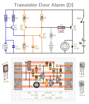
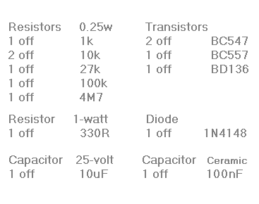
Alarm "D" is an alternate version of circuit "C". It too has both normally-open and normally-closed triggers. And the standby current is about 2uA. But the moving parts of the relay have been replaced by a transistor switch. The BD136 power transistor will reliably switch 500mA without a heatsink.
circuit from http://www.zen22142.zen.co.uk/ronj/lat.html


 This category